Today, the design aspect of the project has reached completion. One major hiccup required a re-design. The initial concept and final projects are both great. If we had the ability to use more materials, we could have done the first design mentioned in previous posts.
But here are the events in order of occurrence:
After designs were reviewed, a selection was chosen. After a few modifications, the project looked great. The materials we will be cutting are translucent so the objects properties were modified through Solid-works. This was similar to an assignment and a pre-lab we were given earlier this semester.

The Lego Pontoons are purchased and are coming from Canada. Can't wait to see them. I am a little disappointed that I couldn't get measurements for the connections so we may just have to find another way to attach the pontoons with the 2-D cut top...
From here, we had to apply the steering mechanism. Lego parts were selected as the bast option. SO the designing began. After deciding a sleeve would be the best option, a design was submitted for the sleeve. Although the sleeve was designed adequately, it is not used. Notice the overall length of boat has been modified. It became apparent that the materials required were too much. And growing.

So a re-design was in order. All the lessons and back door techniques i had used to create the first boat made this process much easier and much less time consuming. Therefore, I actually had a great amount of fun really getting this as close as I could to material and time dedication restrictions given today's date. So I created the hull first. I created a flat shape for each side so all could easily be cut out by the 2-D cut process. I also did the same thing for the cap to the hull, the connector pieces and the Lego pontoon caps.

The Steering system was much easier to put together given I had created a key chart of measurements for the Lego parts as a reference. I also created the rudders using a form from a Lego piece. And there were less moving parts to create added resistance and make it harder for the boat to turn while it is moving through the water.

And the final product looks amazing in my opinion. There will be some angular cuts to be done once the 2-D cuts are completed, but that shouldn't be too hard. A team member has stated to have tremendous talents with plastic welding so it will be his task to connect all the pieces together so that it resembles the photo that follows.

As requested, the 2-D cuts require a certain type of drawing from the top so I created a document to enable them to initiate the project. The next images showcase the drawing from a top view perspective and the 3-D view of what the parts will look like as if all waste material was removed.


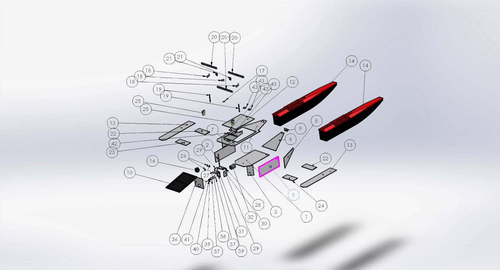
The next images are exploded views with 'Bill of Materials' lists added.


I want to mention the last photo. The motor assembly. The thought of the concept was to create a long enough sleeve over the shaft so a connection can be made between the motor in our spark fun kits and the propeller for a toy boat. At the same time, the long shaft would act to increase stability of drive shaft itself. A rubber ring 15 mm in diameter will be held in pace by a 3-D printed shell as part of the project. The connection from the sleeve to the final axle will also be printed. And the final item to be printed will be the rudders. All items maintained under 4 cubic inches of material.


All pieces that require angle cuts will be submitted in the next post.
Best regards,
Bobby Fisher
No comments:
Post a Comment