Saturday, December 14, 2013
Wednesday, December 11, 2013
Putting The Boat Together + IR Code
Today, all three group members met in order to put our 2D cutouts together.

 We are still waiting for our 3D parts so not everything can be put together today. Nonetheless, this was a good step of progress in finally putting our pieces together.
I also worked on code for the IR remote since we still don't know if using Bluetooth is viable. However I do think the IR remote is the best way to go. With this code (assuming it works perfect), all that needs to be added are the hexadecimal codes for each button [a quick test solves this] and the light code we already have working.
The basic premis of the code is that buttons 0-9 on the remote will represent different speeds and the left/right arrows will indicate direction. All of our other ideas can be implemented (boat path patterns, adjusting light brightness, etc.) once we get this to work properly and get it in water!
- Mike Igoe
Tuesday, December 10, 2013
Meeting to Finish Things Up
Today Bobby and I met in the computer lab in a meeting that is about finishing up the project. First, we discussed the laser cut parts we received and the various problems that were discovered with them.

For the most part, our meeting was based on what needed to be done next since there wasn't much that can be done at the moment. First what we want to do is assemble all our laser cut pieces together. We are meeting with William tomorrow morning and doing this with the Marine Epoxy mentioned in the previous post. This will keep our vessel together as well as water proof.
Next we are still waiting for our 3D printed parts that will complete our assembly and final word if Professor Sullivan is able to get the Bluetooth to work. The 3D parts should be done soon. If the Bluetooth doesn't work, we will have to revert to using IR controllers instead.
So at the moment we are still just waiting for most of the work to be done and have our code to be tested and debugged. Here is my code for the servo motor that we talked about in our meeting. Bobby mentioned how two pins could be utilized, however thinking about it, if we initialize the position to be at 90 degrees in the setup, do we really need to use two pins for 0-90 and 90-180 degrees?
All our parts thus far
All the problems can be solved with relative ease; one problem requires the piece to be filed whilst another requires being cut again to make the hole larger. Many pieces came out perfectly however so it was a large success. We also picked out the propeller from three choices, with the victor being the one with bigger blades.For the most part, our meeting was based on what needed to be done next since there wasn't much that can be done at the moment. First what we want to do is assemble all our laser cut pieces together. We are meeting with William tomorrow morning and doing this with the Marine Epoxy mentioned in the previous post. This will keep our vessel together as well as water proof.
Next we are still waiting for our 3D printed parts that will complete our assembly and final word if Professor Sullivan is able to get the Bluetooth to work. The 3D parts should be done soon. If the Bluetooth doesn't work, we will have to revert to using IR controllers instead.
So at the moment we are still just waiting for most of the work to be done and have our code to be tested and debugged. Here is my code for the servo motor that we talked about in our meeting. Bobby mentioned how two pins could be utilized, however thinking about it, if we initialize the position to be at 90 degrees in the setup, do we really need to use two pins for 0-90 and 90-180 degrees?
Monday, December 9, 2013
In regards to how to construct a model boat hull the same considerations must be processed as if you were building a full size boat. But the best solutions to how to make it are quite different due to size. This points that must be considered are shape, assembly, and sealing.
The options available for shape include making the hull out of one piece, constructing out of multiple shaped pieces, or construction out of multiple flat pieces. For the size we are working in the ultimately superior method would be to make a single piece that is exactly the size a shape we need. This bypasses the need for assembly and sealing entirely. However we could not use this method because we did not have the proper resources to make a piece to the specifications that we needed, so, since we could abundantly make flat pieces that was the method we were somewhat forced into.
Now the real challenges of boat building: assembly and sealing. Assembly is perhaps the part of construction that has the most options, and those options have many sub-options. Speaking of acrylic alone there is bolting, welding, taping, locking, and gluing. Let’s look at each of these and why I choose to use or not use each.
Bolting: the principle of bolting is to connect two pieces by putting a nail or such through them. This is perhaps the sturdiest option but was ultimately not even under considerations because since the pieces we were connecting were small and at angles with each other this would maximize the stress concentrations and would like likely break the pieces with no time to fabricate new ones. Also who wants to punch holes in the bottom of a boat? Not me.
Welding: plastic welding is a great way to connect pieces of acrylic together. A strip of plastic is placed in the interconnecting crevice and a large amount of heat is applied to melt the strip to the pieces. This forms a strong permanent bond that is smooth and easily seal-able. It is, however, relatively dangerous because of burns. But I am fairly experienced in this so that is not likely to be an issue. We were going to be using this method, but we were not able to procure a heat gun in time for construction so we had to switch.
Taping: the principle of taping is very simple; a thin strip of polymer is applied with an adhesive. This strip is then placed across the crevice attaching the pieces together. This method has numerous shortcomings however. The seal is very hard to make tight and is also prone to deterioration in a matter of days. This is great for temporarily and quickly attaching things but not for the work we are doing.
Locking: locking requires no eternal attachment to construct; the geometry of the bodies is simply designed to interconnect. This method generally makes loose connections that are still quite sturdy. However complicating geometry both makes sealing impossible and fabrication a complex endeavor.
Gluing: an adhesive is applied to the surfaces which will attach them. This method is extremely simple mechanically. There are thousands of glues available that can do anything from drying in seconds to holding literally multiple tons of weight. We chose this method because it caused the least complication with sealing and could create a very strong bond.
Sealing our hull is important because we a holding quite a lot of expensive electronics in it. The simply best way of sealing a crevice is to apply a silicone based gel that expands to fill the crack to form a water proof bond. The glue that we will be using is a marine epoxy rated for underwater use, however we will still be applying silicone because you are better safe than sorry.


package of epoxy
William Cooper
Wednesday, December 4, 2013
Coding
After a long time struggling with GitHub and the alien
terminology (forking, committing, bashing, etc.) that goes with it, I finally
found out how to put my code on there. First to tackle was the problem of
implementing the LED lights to blink without using a 2 second delay that would
disrupt all other functionality. My code focused on using iterations of the
loop function as a counter that would go up to two seconds and, upon reaching
that count, execute the light turning on/off. This is seen here:
The issue with this was that you needed to know just how
long it takes for a loop function to execute – I estimated on the low side and
figured I could raise the counter limit until it equated to 2 seconds. Bobby
figured out a way that would both avoid multiple tests as well as the loops:
I also worked on coding the servo motor and ac motor so that
their movements would respond to a potentiometer. This was a test that prepare
us for integrating the motors with the iPhone interface – since the adjustment
of the potentiometer is similar to that of the app. Each is shown below:
Bobby then put the blinking light code together with the
servo code so it was all in one. All that would be needed now is to add the
motor in this:
Finally Bobby introduced a unique idea to use the light
sensor for the LED in place of the potentiometer – that way, the screen would
adjust itself according to the amount of light around it:
With this code we still have the trouble of connecting it to
the iPhone app, however. More work will need to be done before any of this can
be tested and debugged, but so far it looks good.
- Mike
- Mike
-
Friday, November 29, 2013
Hello Everyone.
Today, the design aspect of the project has reached completion. One major hiccup required a re-design. The initial concept and final projects are both great. If we had the ability to use more materials, we could have done the first design mentioned in previous posts.
But here are the events in order of occurrence:
After designs were reviewed, a selection was chosen. After a few modifications, the project looked great. The materials we will be cutting are translucent so the objects properties were modified through Solid-works. This was similar to an assignment and a pre-lab we were given earlier this semester.

The Lego Pontoons are purchased and are coming from Canada. Can't wait to see them. I am a little disappointed that I couldn't get measurements for the connections so we may just have to find another way to attach the pontoons with the 2-D cut top...
From here, we had to apply the steering mechanism. Lego parts were selected as the bast option. SO the designing began. After deciding a sleeve would be the best option, a design was submitted for the sleeve. Although the sleeve was designed adequately, it is not used. Notice the overall length of boat has been modified. It became apparent that the materials required were too much. And growing.


Today, the design aspect of the project has reached completion. One major hiccup required a re-design. The initial concept and final projects are both great. If we had the ability to use more materials, we could have done the first design mentioned in previous posts.
But here are the events in order of occurrence:
After designs were reviewed, a selection was chosen. After a few modifications, the project looked great. The materials we will be cutting are translucent so the objects properties were modified through Solid-works. This was similar to an assignment and a pre-lab we were given earlier this semester.
The Lego Pontoons are purchased and are coming from Canada. Can't wait to see them. I am a little disappointed that I couldn't get measurements for the connections so we may just have to find another way to attach the pontoons with the 2-D cut top...
From here, we had to apply the steering mechanism. Lego parts were selected as the bast option. SO the designing began. After deciding a sleeve would be the best option, a design was submitted for the sleeve. Although the sleeve was designed adequately, it is not used. Notice the overall length of boat has been modified. It became apparent that the materials required were too much. And growing.
So a re-design was in order. All the lessons and back door techniques i had used to create the first boat made this process much easier and much less time consuming. Therefore, I actually had a great amount of fun really getting this as close as I could to material and time dedication restrictions given today's date. So I created the hull first. I created a flat shape for each side so all could easily be cut out by the 2-D cut process. I also did the same thing for the cap to the hull, the connector pieces and the Lego pontoon caps.
The Steering system was much easier to put together given I had created a key chart of measurements for the Lego parts as a reference. I also created the rudders using a form from a Lego piece. And there were less moving parts to create added resistance and make it harder for the boat to turn while it is moving through the water.
And the final product looks amazing in my opinion. There will be some angular cuts to be done once the 2-D cuts are completed, but that shouldn't be too hard. A team member has stated to have tremendous talents with plastic welding so it will be his task to connect all the pieces together so that it resembles the photo that follows.
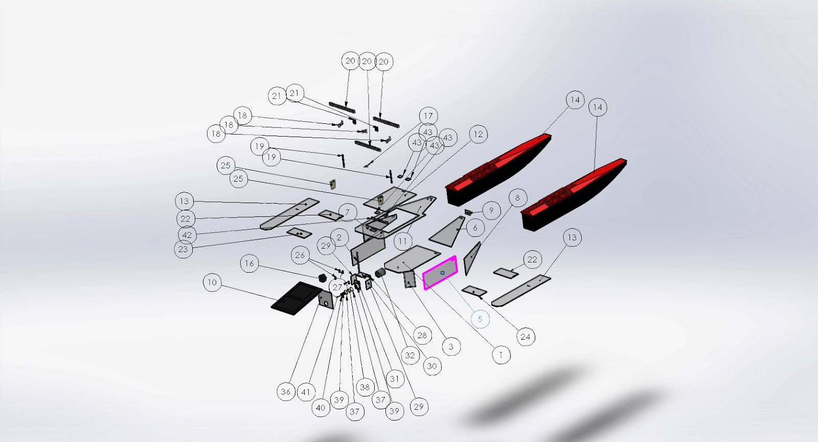
As requested, the 2-D cuts require a certain type of drawing from the top so I created a document to enable them to initiate the project. The next images showcase the drawing from a top view perspective and the 3-D view of what the parts will look like as if all waste material was removed.
The next images are exploded views with 'Bill of Materials' lists added.
I want to mention the last photo. The motor assembly. The thought of the concept was to create a long enough sleeve over the shaft so a connection can be made between the motor in our spark fun kits and the propeller for a toy boat. At the same time, the long shaft would act to increase stability of drive shaft itself. A rubber ring 15 mm in diameter will be held in pace by a 3-D printed shell as part of the project. The connection from the sleeve to the final axle will also be printed. And the final item to be printed will be the rudders. All items maintained under 4 cubic inches of material.
All pieces that require angle cuts will be submitted in the next post.
Best regards,
Bobby Fisher
Saturday, November 23, 2013
Coding Patterns (Ideas)
I believe boat moving patterns can be achieved through mere functions and a coded control of delay and servo-motor (for rudder) values. For example, we would customly create different methods ("void Xpattern(), void Ypattern(), etc.") that can be called through the iPhone GUI interface. Within each method, all that needs to be altered with are the direction which we set the Servo as well as how long we want it in that position (delay).
For a first example, let's take a mere circular pattern:

For this pattern our function would only set the Servo postion to one constant value (say 30 degrees). Our delay value, in this case, would determine only how long the boat would stay in a circular pattern. Experimentation can perfect these values so we can have it leave the circular pattern in any direction desired.
Another neat pattern would be an infinity loop:

Finally, we can take things to be even more complex and try to implement something such as this:

I will post some experimental code snippets on here when I figure out how to use Github....
-Mike
Implements Boat Lights:
In lecture, it was brought up that implementing lights using a delay has the potential to mess up other parts of the code when causing their execution to delay aswell. He mentioned how something else could be purchased to fix this but I think maybe another arduino board can fix it. All that needs to be done is an extremely simple code that can be uploaded on the board and stay in it. It would be an entire seperate entity that just needs batteries to power - however our hull would need room for the board.
Just a thought,
- Mike
Subscribe to:
Comments (Atom)